The following code runs on an Arduino with a 5 button keypad, I2C 4 line 20 character LCD display, 18 NeoPixel ring and a 3 NeoPixel PCB. The NeoPixel components are mounted on 3D printed parts. See TinkerCad links below for the STL files/designs. Also see below for further information on the other parts and an enclosure for the electronics.
// ----------------------------------------------------------------------------
// WS2812B RGB LEDs
// NeoPixel ring & centre - 21 LEDs
// ----------------------------------------------------------------------------

#include <Wire.h>
#include <FastLED.h>
#include <LiquidCrystal_I2C.h>

// -------------------- LCD --------------------
LiquidCrystal_I2C lcd(0x3F, 20, 4);

// -------------------- LEDs -------------------
#define LED_TYPE    WS2812B
#define COLOR_ORDER GRB
#define NUM_LEDS    21
#define DATA_PIN    6
#define BRIGHTNESS  150

CRGB leds[NUM_LEDS];

// -------------------- Buttons ----------------
const byte analogPin = A0;
const int numButtons = 5;
const int tolerance  = 20;

int buttonValues[numButtons] = {0, 143, 505, 328, 740}; // will vary from keypad to keypad!

enum {
  BTN_LEFT  = 0,
  BTN_UP    = 1,
  BTN_RIGHT = 2,
  BTN_DOWN  = 3,
  BTN_SEL   = 4
};

// -------------------- Globals ----------------
uint8_t Red1   = 0;
uint8_t Green1 = 0;
uint8_t Blue1  = 0;

int sector_start = 1;   // UI values: 1–21
int sector_end   = 21;

int key = -1;
int lastKey = -1;
bool stop_flag = false;

// ----------------------------------------------------------------------------
// Read button (raw)
// ----------------------------------------------------------------------------
int which_button()
{
  int analogValue = analogRead(analogPin);
  for (int i = 0; i < numButtons; i++) {
    if (abs(analogValue - buttonValues[i]) <= tolerance) {
      return i;
    }
  }
  return -1;
}

// ----------------------------------------------------------------------------
// Read button (edge-triggered)
// ----------------------------------------------------------------------------
int getKeyPress()
{
  int k = which_button();
  if (k != -1 && k != lastKey) {
    lastKey = k;
    return k;
  }
  if (k == -1) lastKey = -1;
  return -1;
}

// ----------------------------------------------------------------------------
// Setup
// ----------------------------------------------------------------------------
void setup()
{
  FastLED.addLeds<LED_TYPE, DATA_PIN, COLOR_ORDER>(leds, NUM_LEDS);
  FastLED.setBrightness(BRIGHTNESS);

  lcd.init();
  lcd.backlight();
  lcd.clear();

  lcd.setCursor(0, 0); lcd.print("   P.Mobbs LumiLED  ");
  lcd.setCursor(0, 1); lcd.print("NeoPixel Illuminator");
  lcd.setCursor(0, 2); lcd.print("Software version 2.4");
  lcd.setCursor(0, 3); lcd.print("    29th Dec 2025   ");
  delay(2000);

  fill_solid(leds, NUM_LEDS, CRGB(50, 50, 50)); // start with all leds set to white
  FastLED.show();
}

// ----------------------------------------------------------------------------
// Main loop
// ----------------------------------------------------------------------------
void loop()
{
  stop_flag = false;
  sector_start = 1;
  sector_end   = NUM_LEDS;

  lcd.clear();
  lcd.setCursor(0, 0); lcd.print("     Set Sector     ");
  lcd.setCursor(0, 1); lcd.print("Sector start: ");
  lcd.setCursor(0, 2); lcd.print("Sector end:   ");

  while (!stop_flag)
  {
    key = getKeyPress();

    switch (key)
    {
      case BTN_LEFT:
        sector_start = max(1, sector_start - 1);
        break;

      case BTN_RIGHT:
        sector_start = min(NUM_LEDS, sector_start + 1);
        break;

      case BTN_UP:
        sector_end = min(NUM_LEDS, sector_end + 1);
        break;

      case BTN_DOWN:
        sector_end = max(sector_start, sector_end - 1);
        break;

      case BTN_SEL:
        stop_flag = true;
        break;
    }

    lcd.setCursor(17, 1); lcd.print("  "); lcd.setCursor(17, 1); lcd.print(sector_start);
    lcd.setCursor(17, 2); lcd.print("  "); lcd.setCursor(17, 2); lcd.print(sector_end);
  }

  SetRGBBr();
}

// ----------------------------------------------------------------------------
// Set colour & apply to sector
// ----------------------------------------------------------------------------
void SetRGBBr()
{
  Red1 = Green1 = Blue1 = 0;
  stop_flag = false;

  lcd.clear();
  lcd.setCursor(0, 0); lcd.print("   Keep sectors ?   ");
  lcd.setCursor(0, 1); lcd.print(" Left=N  Right=Y ");

  while (!stop_flag)
  {
    key = getKeyPress();

    if (key == BTN_LEFT) {
      fill_solid(leds, NUM_LEDS, CRGB::Black);
      FastLED.show();
      stop_flag = true;
    }
    else if (key == BTN_RIGHT) {
      stop_flag = true;
    }
  }

  stop_flag = false;
  lcd.clear();
  lcd.setCursor(0, 0); lcd.print("     Set colours    ");
  lcd.setCursor(0, 1); lcd.print("(L) Red   = ");
  lcd.setCursor(0, 2); lcd.print("(U) Green = ");
  lcd.setCursor(0, 3); lcd.print("(R) Blue  = ");

  while (!stop_flag)
  {
    key = getKeyPress();

    if (key == BTN_LEFT)   Red1   = (Red1   + 5) % 256;
    if (key == BTN_UP)     Green1 = (Green1 + 5) % 256;
    if (key == BTN_RIGHT)  Blue1  = (Blue1  + 5) % 256;
    if (key == BTN_SEL)    stop_flag = true;

    lcd.setCursor(13, 1); lcd.print("    "); lcd.setCursor(13, 1); lcd.print(Red1);
    lcd.setCursor(13, 2); lcd.print("    "); lcd.setCursor(13, 2); lcd.print(Green1);
    lcd.setCursor(13, 3); lcd.print("    "); lcd.setCursor(13, 3); lcd.print(Blue1);

    // Convert UI indices (1–21) to LED indices (0–20)
    int startIndex = sector_start - 1;
    int count      = sector_end - sector_start + 1;

    fill_solid(&leds[startIndex], count, CRGB(Red1, Green1, Blue1));
    FastLED.show();
  }
}
The parts required can mostly be obtained from AliExpress. I used a genuine Arduino Uno R3 but imitations will work and it should be relatively easy to adapt the design to run on other Arduino or ESP32 boards. A warning: do not undertake this project unless you are familiar with Arduinos, basic electronics and how to solder. You undertake the build entirely at your own risk. I cannot offer to help if the project does not work!
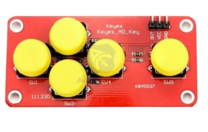
The main components apart from an Arduino Uno are a 5 button keypad like this one:
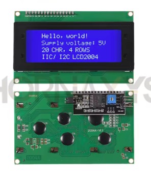
A 4 line 20 character LCD display with an I2C interface. Like this:
You will also need a power supply for the Arduino with the capability to separately supply the NeoPixel components with 5V at up to 1A. I use one of these:
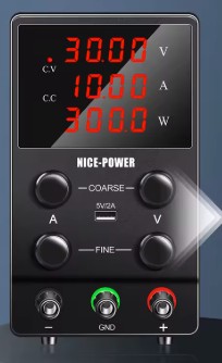
The power supply above comes with various name labels. I suspect they are all the same but I cannot be sure. Mine is labelled ‘Ruzizao’. I use the USB A output to power the Arduino and the main output set to 5V to power the LEDs. Using more than 5V will burn out the LEDs. I do not recommend setting the BRIGHTNESS value in the program above to values greater than 150. IMPORTANT – you can use other power supplies but they must share a common ground. It is also possible to use a single ‘wall wart’ power supply at say 12V and a down converter to provide power to the NeoPixels. Some switching power supplies may not operate at a high enough frequency to prevent ‘banding’ on digital cameras.
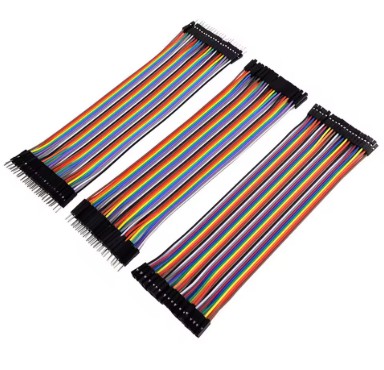
You will also need some jumper leads and an optional ON/OFF switch. The switch is used to power down the NeoPixel components. It goes in the +ve line supplying the LEDs. If I run the LEDs at high RGB values I switch them off after a few seconds to avoid heat build up. Jumper leads (DuPont connectors) like this are handy (pin to socket):
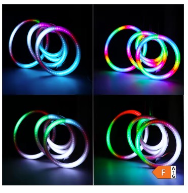
The NeoPixel rings with a diffuser are 27mm in diameter with a 12mm hole in the middle. They have 18 RGB pixels and a built in diffuser. They look like this:
The 3 NeoPixel PCB (17mm in diameter) looks like this:

You will need to use either jumper leads or to buy two 18 LED rings and cannibalize one for the connector in order to make the connection between the 18 NeoPixel Ring and the 3 NeoPixel PCB.
I modified this ‘Trinity’ three-part case https://www.thingiverse.com/thing:1159729 by ‘usermod’ (thank you usermod!). I modified the button panel to take the keypad shown above – you can find that modification here:
https://www.tinkercad.com/things/imXV63tEuq9-trinityboxfaceplate5buttonpad3

The button panel for ‘Trinity’ case. You may need to ‘tinker’ this to get a good fit to your keypad – the button pads seem to vary a bit.
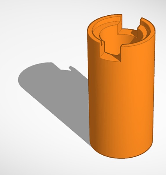
Outer tube of the illuminator that carries the 18 NeoPixel ring. This can be held in place with a zip tie across the input and output cables or it can be superglued in place. The tube illustrated is for the Bresser Infinity microscope. I have not made this design ‘Tinkerable’. Use the Nachet link if you want to tinker.
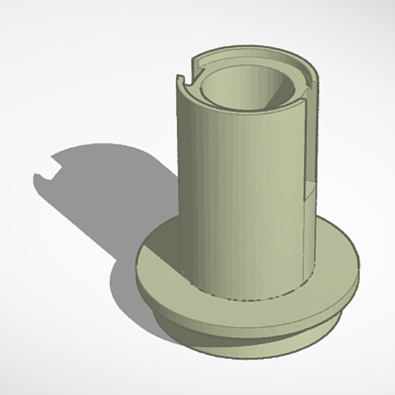
Inner tube that carries the 3 LED PCB. Its a push fit but superglue may be required.

The spacer/reflector ring should be printed in white. It’s a push fit inside the inner tube of the illuminator and spaces the diffusion plastic from the NeoPixel PCB.
The 3d printed parts for the illuminator can be found here:
Outer tube: https://www.tinkercad.com/things/dHjtgKnUYDF-nachetledcondenser3
https://www.tinkercad.com/things/iYeYoJgIME5-bresserouterluciledilluminator
Inner tube: https://www.tinkercad.com/things/9SD5LDd7yj7-lucigencentreledcondenser
Reflector/spacer: https://www.tinkercad.com/things/5jczNqMwPtA-lumiledspacer
The reflector should be printed in white. All the other parts in matte black. I used PLA with standard infill and a 0.4mm nozzle. Supports are required in order for the flanges to print correctly.
The illuminator also a disc of opal white plastic that acts as a diffuser for the central 3 LEDs. I cannot give a source for this because I cut one from the cover of an old plastic filing folder! It needs to be reasonably transparent but to also act as a good diffuser – its properties need to be rather like a thin cigarette paper.
Leave a Reply